Introduction
In modern engineering and design, Computer Numerical Control (CNC) and Computer Aided Manufacturing (CAM) are important skills to have. One machine that exemplifies these concepts is the CNC router.
The Project: Marble Maze
In order to gain experience in CNC and CAM, I constructed a maze using a CNC router. The constraints are as follows:
- The maze will be made of 3/4" Styrofoam (and potentially a second wooden version)
- The maze must have maximum dimensions of 8 1/2" x 11"
- A 1/4" border must exist around the perimeter of the maze
- Channels for the ball must be 1/4" wide and 1/2" deep
- Discrete start and end locations must exist
- The entire maze (channels, perimeter, start/finish) will be made using the CNC Router
- A wooden maze may be further designed using the laser cutter
Maze Design
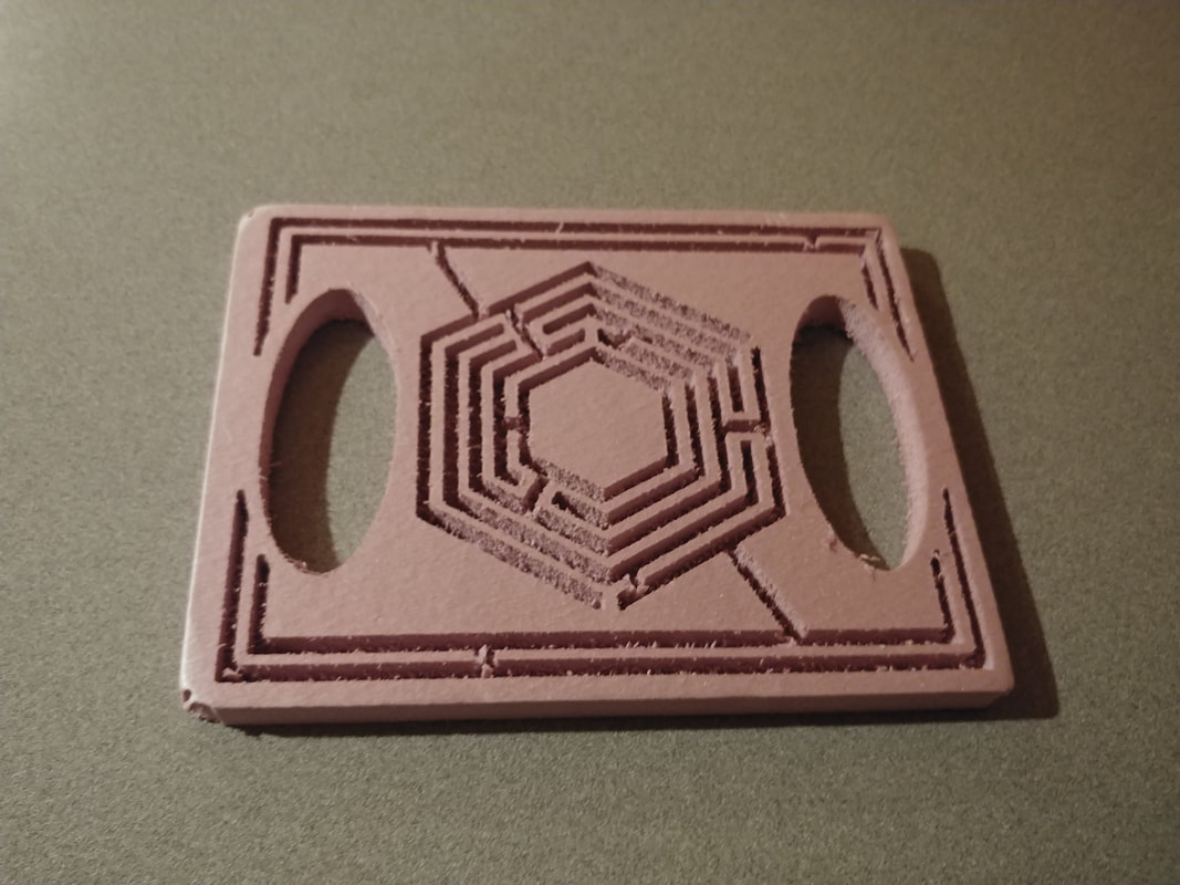
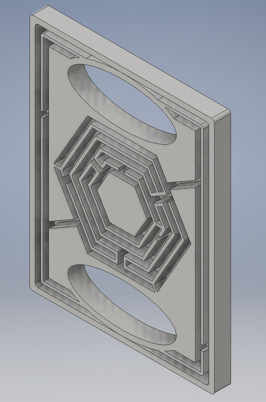
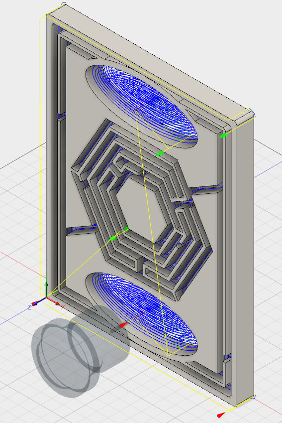
I decided that it would be interesting to have a hexagonal maze. Also, I added handles to the ends of the maze for greater player convenience. The maze begins on the outermost left and ends on the right from the picture shown below.
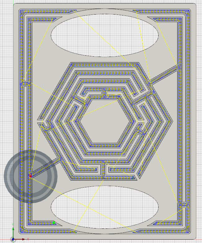
Autodesk Fusion 360 and CAM
After completing the design, I set up a process to mill it in Autodesk Fusion 360. Initially, I used a 2D Adaptive Clearing process for the channels.
Toolpaths Reoptimized
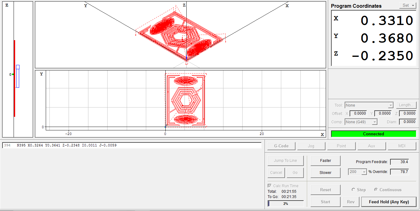
As CNC machines have extreme versatility, there are many different ways to manufacture the same part. In prior iterations of the design, I had used a 2D Adaptive Clearing process to carve the maze channels. However, the 3D Contour process produces the same end result in a fraction of the time. As the entire class is producing mazes with time running out, reducing machine time for each project is vital. Now, my estimated total machine time is about 20 minutes.
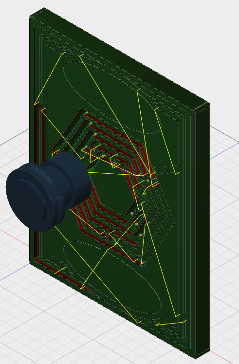
Preparing the Router
Before starting to manufacture something on a CNC router, certain settings must be set up. First, one must pay attention to the axes on which a process is set. Using my maze as an example, its width is along the x-axis, and its length is on y. Therefore, the stock should be prepared in a portrait orientation. Also, as the bottom left corner is the starting point, I must zero the router at that point.
Manufacturing the Maze
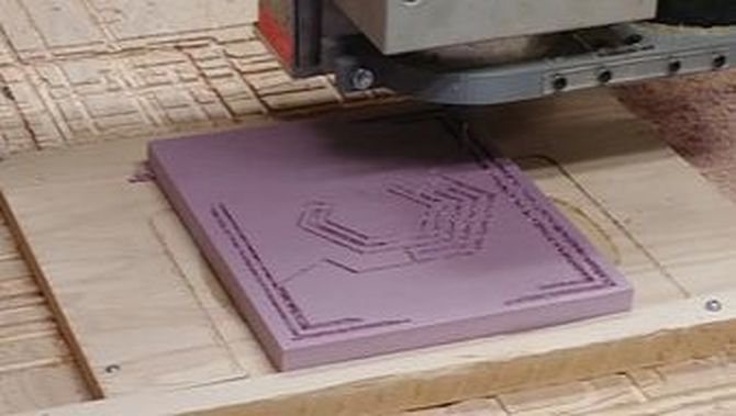
As the router is prepared, I can now manufacture the maze itself in Styrofoam. Given the orientation of the maze in the router's software, I need to place the maze in the portrait orientation. I attached the Styrofoam block to the cutting table using double-sided tape and zeroed the router on the bottom-left point. After pressing "Start," the process completed flawlessly from beginning to end.
Final Product
Thanks to the use of 3D Contour rather than a 2D Adaptive Clearing, the maze cut out quickly. The channels appear rough, but that is only the Styrofoam shavings from the clearing process.